Equipments
Screening
To protect the main units of a treatment plant and aid in their efficient operation, it is necessary to use screens to remove any large floating and suspended solids present in the inflow. These materials include leaves, twigs, paper, rags, and other debris that could obstruct flow through the plant or damage equipment. There are manually cleaned screens and mechanically cleaned screens based on the cleaning operation.
Types of Screens on the basis of Cleaning Methods
- Mechanically cleaned bar screens
- Manually cleaned bar screens
- Manually cleaned fixed bar screens
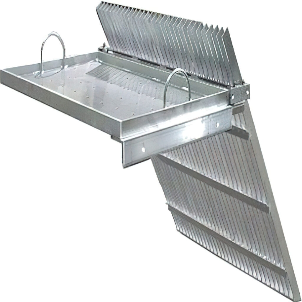
Coarse Screen
It protects pumps, valves, pipe lines, impellers and other related equipment. It is installed at the intake of waste water before pumping, primary settling or grit chamber and is made up of a grid of rods or bars.
Band or Belt Screens
These are flexible woven wire mesh screens installed for a river supply. An adjoining bar screen made up of mild steel is also attached to the flexible woven wire mesh. The movement of these screens is either vertical or horizontal in direction. Jets of water are used from the inside of the screens to remove the debris.
Drum Screen
These screens are made up of hollow drums. The waste water is passed through the inside/hollow portion of the drum. The solid is retained inside the drum and the screenings are removed through gravitational action. Jets of water from outside can also be used to clean the drums through spraying.
Micro screening
These screens are typically low-speed drum screens and referred as the smallest type of screens. The drums are lined with filtering fabrics with opening of 10 to 35µm. Wastewater enters the drum, and the retained solid waste is collected and disposed of.
Fine Screen
These screens are located behind coarse screens and their openings range from 10 – 13mm. These screens prevent passage of small debris such as sticks, barks, leaves, fishes etc.
Fixed Screens
Fine Fixed screens are fit when only modicum of materials need to be removed and are placed just after a bar screen. The screens range from 1 – 25mm
Disc Screens
These screens operate in circular direction. The diameter of these screens ranges from 2 – 5m and move at a speed of about 0.05m/s
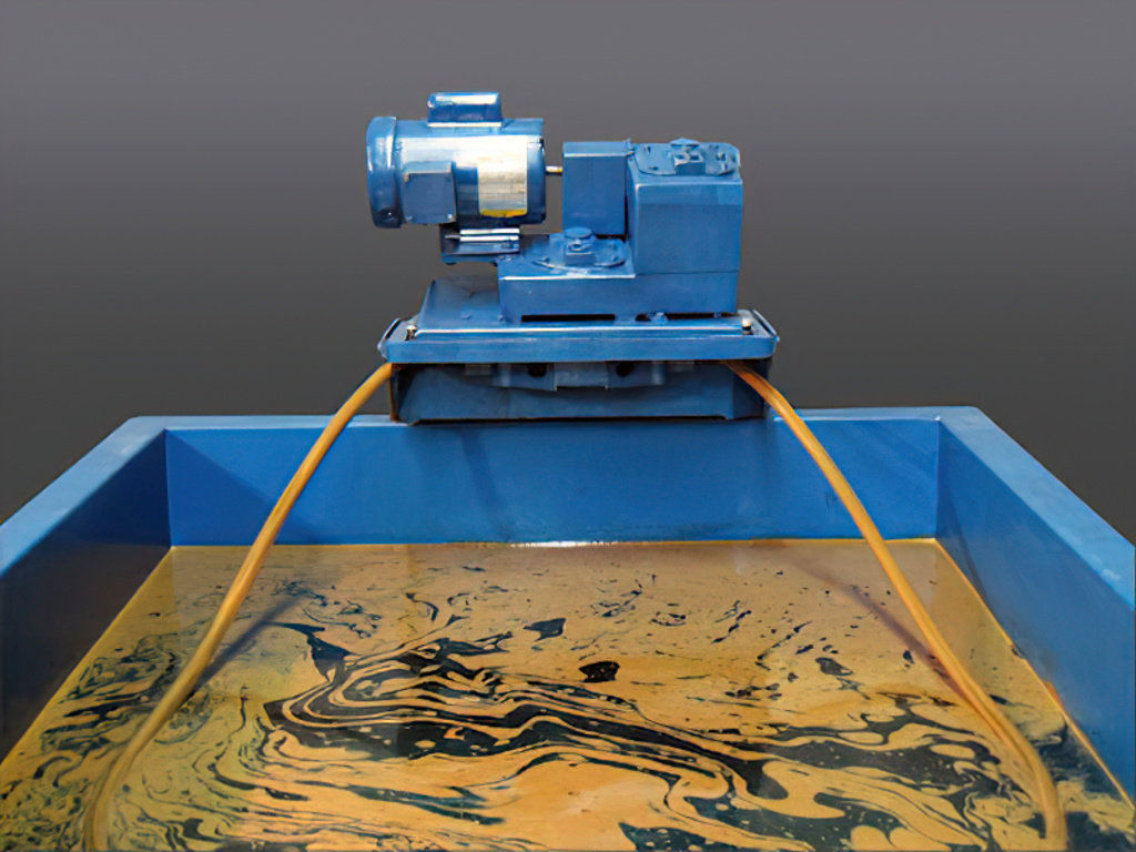
Oil skimmers
An oil skimmer is a machine that removes floating oil and grease from liquid. The floating oil adheres to skimming media, such as a belt, tube, rope, mop, or disk. The media then runs back to the machine to be wiped clean.
Gravity skimmers
Rely upon the difference in specific gravity between the oil and the water or solution. Oil floats to the top and is then removed.
Belt skimmers
Run through a contaminated liquid continuously, using a belt to pick up the oil. Often, a wiper is used to remove the oil from the belt.
Handheld or suction skimmers
Its small, portable devices used in small spaces such as sumps and manholes. A weir or plate is mounted at the bottom of a pipe and lowered by hand to the interface.
Wheel skimmers
Pass a coated disc or wheel through the contaminated liquid. The disc or wheel picks up the oil, which is then skimmed off outside the tank.
Tube oil skimmers
A rope or string is circulated through the contaminated liquid. Tube skimmers can be side-mounted for low clearance applications.
Sponge skimmers
Use absorptive materials that are designed to capture oil, but not water or other filtered solutions.
Centrifuge skimmers
Separate media by spinning, causing the denser material (water) to migrate to the outside where it can be separated.
Floating weir skimmers
Include floats and an adjustable-height weir that can be positioned at the oil-water interface so that contaminants flow into the weir and the water is excluded.
Dosing system
A chemical dosing system is defined as a capacity for mechanical injection of chemicals into a wastewater system for the control of septicity and odour emissions. These systems are typically used at pump stations, sewer manholes, and rising mains.
Parts of a Dosing Apparatus
Although the parts of a dosing apparatus may vary depending on the brand and application, the major components based on functionality and principle can be outlined as:
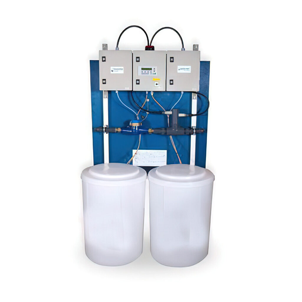
Tank
The container to be dosed.
Foot valve
A input valve (non – reversible) is attached to the suction line and placed into the drum of the product. It is kept at the bottom of the drum, and has a Float Switch attached to it for checking product availability and alarming when the latter runs out.
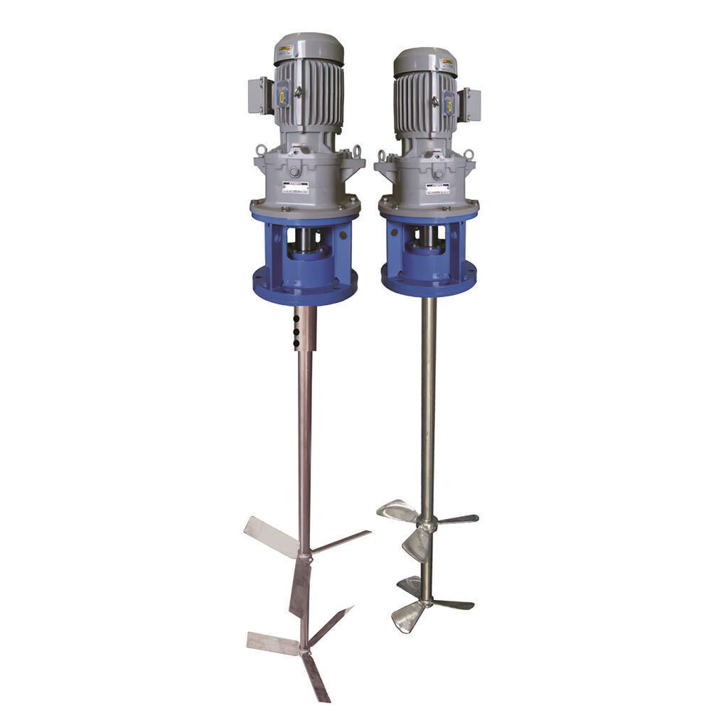
Dosing Pump
Corrosion resistant PVC, PE and other plastics, rubbers and even stainless steel.The suction line attaches to its inlet while a dosing line attaches to the suction line.
Dosing Line
Rigid PVC or PE tube or a reinforced hose, this element produces variety of bleed, pressure relief or air release valves included into it.
Injector
A nozzle that pushes out the precise flux of product supplied by the dosing pump into the line. The injector confirms that the product is delivered to the middle than the side wall of the flow to avoid depletion of product, thorough mixing, and to avoid damaging the walls especially when the fluids are acids or peroxides.
Control System
Modern plants use control systems and software to ensure the dosing pump is accurate and to provide automation. SCADA systems and other central control systems with sensors for pH, chlorine, and similar and variable rate control are used to this end.
4 Types of Dosing pump
- Diaphragm-Type Constant Injection Pump : This is a pump chamber works by a piston on inlets and outlets. When the chamber is full, the dosed volume is injected out at a constant flow rate, generally in the range of 6 – 250 l/hr.
- Diaphragm-Type Pulse Injection : This method is based on a diaphragm mechanism. This pump is controlled by a solenoid coil that sucks in and injects the chemical in pulses. The time-gap between the pulses provide the control of flow rate.
- Lobe-Type Pumps : This design allows the flux to pass through a set of mesh-gear-type impellers.
- Peristaltic Pumps : Peristaltic pumps consist of a flexible tube with a semi-circular cross section.
Flash Mixer
Screening out debris and testing the raw water, the water treatment effectively starts at the flash mix chamber. Here, chemicals are added to the water, primarily to aid in coagulation and flocculation. In the flash mixer, the water is agitated violently for a short period of time before being released into the flocculation basin.
The period of mixing in the flash mix chamber is carefully controlled and is usually between thirty seconds and one minute. When determining the length of time that water must spend in the flash mix chamber, flow rates must be calculated. The volume of the flash mix chamber and the amount of flow determine the contact time.
Flocculator
In this process, a chemical called a coagulant (with a positive electrical charge) is added to the water, which neutralizes the fine particles’ negative electrical charge. The coagulant’s addition takes place in a rapid mix tank where a high-speed impeller rapidly disperses the coagulant.
Since their charges are now neutralized, the fine particles come together, forming soft, fluffy particles called ‘flocs.’ Two coagulants commonly used in the treatment of water are aluminium sulphate and ferric chloride. Here the water is gently stirred by paddles in a flocculation basin, and the flocs come into contact with each other to form larger flocs.
There are 6 types being engineered
- Hydraulic Baffled Wall Flocculator
- Hyperbolic Flocculator
- Impeller Flocculator
- Vertical Paddle Wheel Flocculator
- Horizontal Paddle Wheel Flocculator
- Walking Beam Flocculator
The flocculation basin often has a number of compartments with decreasing mixing speeds as the water advances through the basin. This compartmentalized chamber allows increasingly large flocs to form without being broken apart by the mixing blades.
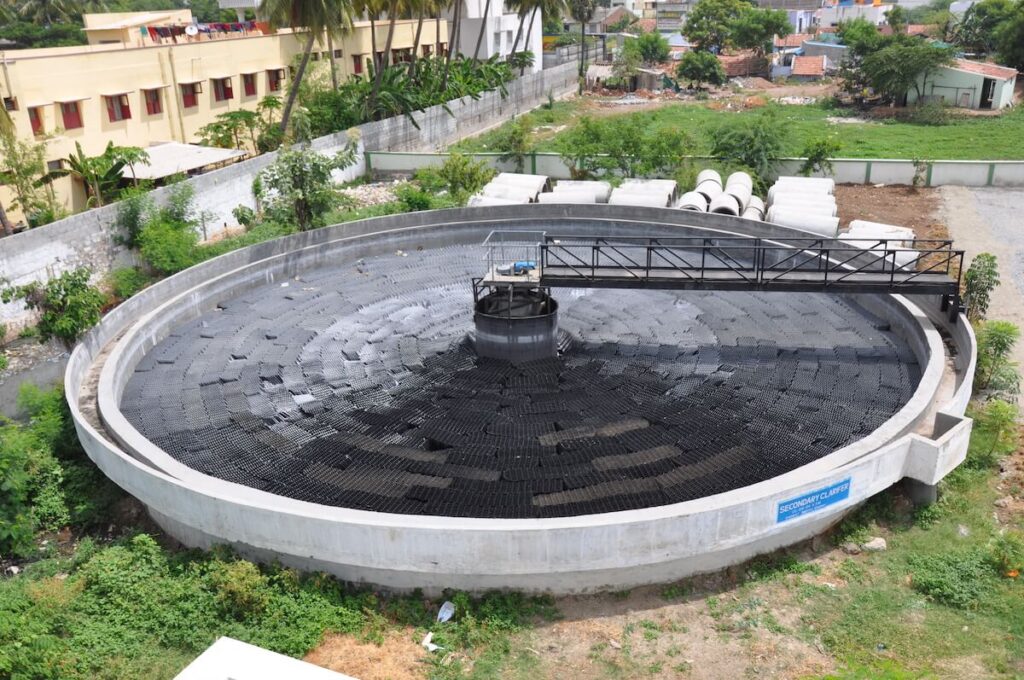
Clarifier mechanism
Clarifiers are settling tanks built with mechanical means for continuous removal of solids being deposited by sedimentation. A clarifier is generally used to remove solid particulates or suspended solids from liquid for clarification and/or thickening. Concentrated impurities, discharged from the bottom of the tank are known as sludge, while the particles that float to the surface of the liquid are called scum.
Bridge Support Clarifier
In a bridge-supported wastewater clarifier, the sludge removal system is mounted beneath a bridge-like structure, which spans from one side of the tank to the other. This is suitable for tanks of up to 45 inches in diameter — any larger than this, and it becomes uneconomical to install a bridge that is robust enough to do the job safely and securely.
Traction Clarifier
Traction clarifiers are mounted on a central column in the same way as a column support clarifier, but this column is designed to pivot. A gearbox and slip ring mounted within this central column provides the torque force, rotating the column and moving the clarifier arm through the tank. The clarifier arm extends across the full radius of the tank (half of the diameter) and is supported by a traction trolley at the tank’s perimeter.
Column Support Clarifier
This type of clarifier is supported by a column, also known as a pier, mounted at the bottom of the center of the tank. Column-supported clarifiers are suitable for larger tanks, often up to 250 inches in diameter.
Clariflocculator
The clariflocculator is a secondary treatment unit, both for water treatment as well as wastewater treatment. A clarifier is also the main unit of many treatment processes. As a single unit covers a large area and as many as 12 clariflocculators are used on a plant, its design needs to be efficient as well as effective to justify the space. One unit performs 4 processes which makes the design even more critical.
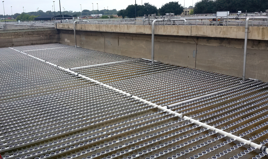
Diffused Aeration System
The water then is aerated (supplied with air) by passing it over a series of steps to take in oxygen from the air. This process helps in expelling soluble gases such as carbon dioxide and hydrogen sulphide (both of which are acidic, so this process makes the water less corrosive) and expels any gaseous organic compounds an undesirable taste to the water.
Aeration also removes iron or manganese by oxidation of these substances to their insoluble form. Iron and manganese can cause peculiar tastes and can stain clothing. Once in their insoluble forms, these substances can be removed by filtration.

Filters
Once effluent has been treated in the primary and secondary stages by removing suspended solids, pH balancing and reducing its biochemical oxygen demand (BOD), it is ready to enter the tertiary stage. The process usually involves filtration followed by additional disinfecting treatment.
- Dual Media Filters - Dual Media Filter is used for removal of suspended solids, turbidity, colour and odour from Water & Wastewater. Water to be treated is passed through the filter containing anthracite along with fine sand strengthened by marbled and gravels, the largest particles are strained out by the anthracite then the sand traps the rest of the particulate matter though a combination of adhesion and straining. Since the particles in the water are filtered out at various depths, the filter does not clog as quickly as all of the particles were caught by the top layer.
- Pressure Sand Filters - Sand filtration is frequently used and very robust method to remove suspended solids from water. The filtration medium consists of a multiple layer of sand with a variety in size and specific gravity. Sand filters can be supplied in different sizes and materials both manual or automatic.
- Activated Carbon Filters – Charcoal, in other words carbon, is treated with oxygen. Small pores are opened between the carbon atoms resulting in absorption of impurities from liquid and gases. Organic matters, chlorine, and disinfectants are removed from water with the help of activated charcoal filters. They are also known to enhance the taste of water. Using this process before any other filtration process such as reverse osmosis, saves oxidation.
- Iron Removal Filters - The Iron Removal Filters are designed to remove the Excess Iron content present in the feed water with minimum pressure drop. Iron filtration systems operate on the principal of oxidizing the iron (oxidation) to convert it from a ferrous (dissolved or soluble) to a ferric or undissolved state.
- Softeners - Water softening is a technique that serves the removal of the ions that cause the water to be hard, in most cases calcium and magnesium ions. Iron ions may also be removed during softening. ... A water softener is a unit that is used to soften water, by removing the minerals that cause the water to be hard.
- Particle Filtration - Particle filtration is a system that separates solids from liquids using either physical or mechanical means. When it comes to wastewater treatment, particle filtration is commonly one of the first steps in the treatment of contaminated wastewater. This is because particle filtration is designed to remove solids measuring larger than one micron.
Bag filters are a great option for smaller applications and systems where minimizing waste is important. As the name suggests, bag filters are in the shape of an elongated bag. Wastewater goes into the bag, where the solid particles from the water are caught, allowing only clean water to flow through the bag’s pores to the other side.
Cartridge filters come in many different materials, shapes, and ratings. Some examples include pleated, melt-blown, string-wound, and membrane, with ratings from 100 micron to less than 1 micron. Utilizing pleated fabric or another type of screen, cartridge filters are a modular type of filter, meant to trap particles and even chemicals through the filtration process. Cartridge filters are typically separated into two categories: surface filters and depth filters. Surface filters retain particles on the surface of the liquid, while depth cartridge filters use a thick media, meant to create a twisted path that retains particles. Cartridge filters are considered to be very versatile and are used in a wide number of applications.
Commonly considered one of the most useful aspects of these filters, their ability to clean themselves sets them apart from other filters. Highly demanded and able to be customized with a number of different sizes and materials, self-cleaning filters are ideal within systems that cannot be shut down for cleaning purposes. Self-cleaning filters typically utilize backwashing or mechanical processes for the purposes of removing debris.
Disinfection
Following the filtration process, the water is almost treated with crystal clear in appearance. However, there might still be the presence of bacteria and viruses in them. To destroy them, a disinfection is process employed.
Chlorination
Chlorine comes in many different forms including chlorine gas (most common), chlorine dioxide, hypochlorite (bleach), and others. Whichever method is used, chlorine is added to the water in an amount to ensure all microorganisms are destroyed. Water plants monitor the chlorine levels continuously and very carefully in the treated water.
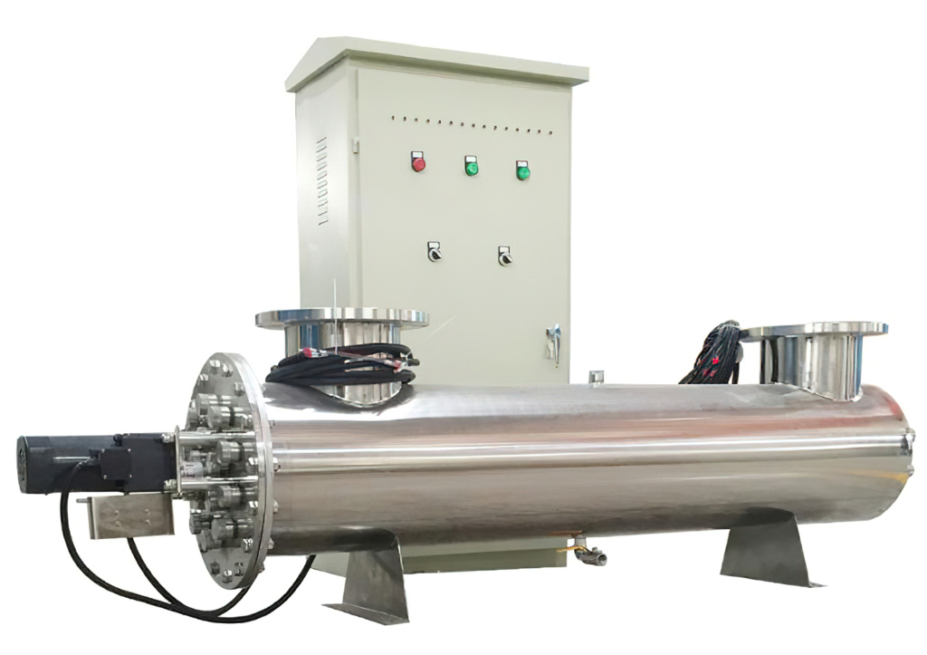
UV
Ultraviolet light of wavelength 253.7 nanometers is used for disinfection of bacteria, viruses, moulds, algae, and other microorganisms, which multiply and grow. UV disinfection technology destroys the DNA of microorganisms which leaves them dead and unable to grow further.
Ozone
Ozone is produced when oxygen (O2) molecules are dissociated by an energy source into oxygen atoms and subsequently collide with an oxygen molecule to form an unstable gas, ozone (O3), which is used to disinfect wastewater.
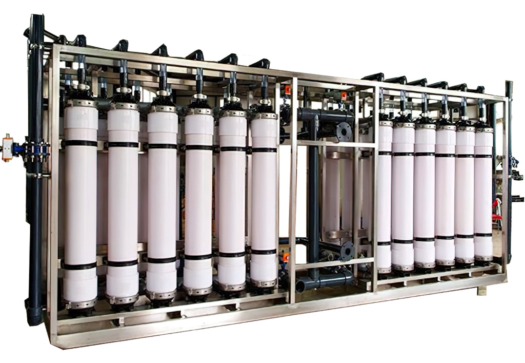
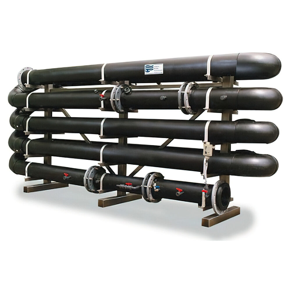
Ultra – filtration
Ultrafiltration (UF) is a water purification process in which water is forced through a semipermeable membrane. Suspended solids and high-molecular-weight solutes remain on one side of the membrane, the retentate side, while water and low-molecular-weight solutes filter through the membrane to the permeate side.
Reuse & recycling
Storage
Once the disinfection process is complete, the water is stored. Storage usually takes place in an underground storage tank called a “clear well”, and also in elevated storage tanks that are visible around town.
Distribution
The stored water is pushed through underground pipelines all over town in what is called a “distribution system”. The distribution system consists of large water pumps at the treatment plant, overhead water storage tanks, large pipelines, smaller pipelines, fire hydrants, valves, and water meters in your front yard.
Enquiry Form
Please fill out the form below and allow 48 business hours for our reply. We look forward to responding to your query.